
When you need reliable protection against contamination, erosion, and chemical spills, we offer a wide range of ready-made materials and custom-fabricated solutions. Our team of experts is on hand to help you choose the right containment system for your specific application, ensuring optimal performance coupled with the longevity you need.
Advanced Solutions
You will find that ITL is able to supply liner and geotextile for a multitude of applications, including: Drilling & Completion Pads, Secondary Containment Ponds & Impoundments, Pits for Stormwater Runoff, Irrigation & Sediment Ponds, Landfills for Soil & Trash, Hazardous Waste, Lagoons, and so much more.
Liner Options include: ITL Coated Woven Polyethylene LLDPE and HDPE Smooth, Textured, Black, Gray, and White Single-Piece Liner for Larger Projects─up to 5,000 kg
Non-Woven Geotextile Options include: 4 oz. to 24 oz. Non-Woven Felt Underlayment Roll Stock or Custom Fabrication to meet the project configuration.

AST One Piece Liners
ITL offers one piece stepped liners for potable or freshwater storage. Oil and Gas applications include the storage of brine and specialty liners for oil and condensate. Covers are fabricated by our team to meet your specifications.
LLDPE Solutions Include:
- Wider base goods for fewer plant fabricated seams, reducing environmental risks.
- Special resins for LLDPE flexibility.
- Proven industry performance in extreme hot and cold weather.
- ITL custom CAD capabilities.
- Resources to meet each customer’s project specifications.

Containment Walls
Engineered specially for secondary containment and spill prevention, Poly Dike MPE walls are for short-term or long-term applications. The modular design makes installations very easy and efficient. The Poly Dike MPE walls are light weight, flexible and require no hand tools or heavy equipment for installation.
- Multiple Size Options.
- Multiple Configuration Options.
- Wall Heights from 0.3 m to 1.22 m.
- Portable walls that can be reusable for short and long term applications.
- One-piece and single-panel felt are fabricated as part of the ITL turnkey Containment Solutions.

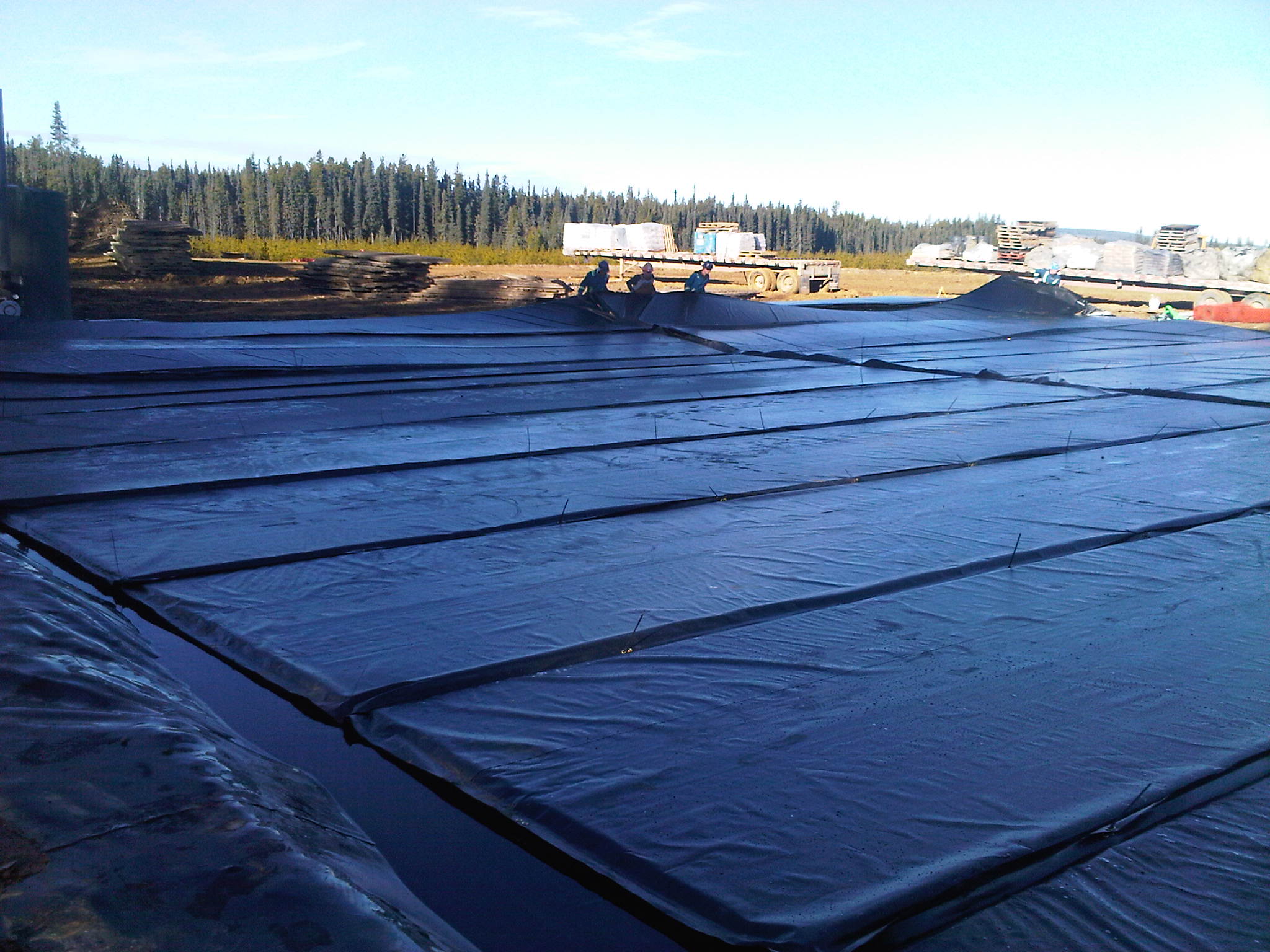
Well Pad Liners, Drilling & Completion Pads
Coated Woven Polyethylene (CWPE) is the perfect material for your pad liner applications. Our XGL series are extremely durable, with an anti-slip surface, and high puncture strengths that will withstand direct traffic. Protect the entire pad with large single piece fabricated CWPE panels requiring limited to no field seaming.
Well Pad Liner solutions from ITL have many benefits, including:
- 100% Recyclable
- Reinforcement—5, 6, & 8 layers thick
- Multi Scrim/Multiple Strength (X symbol)
- Lighter and Stronger than LLDPE & HDPE
- Plant Fabricated and Tested— significantly reduces time and weather related issues for in-field seam welding)
- No Geotextile Underlayment**— considerable time savings, reduced labor, less material to recycle or landfill
- Offers Field Repair Advantages
- Reusability—dependent on application & area
Well Pad Liner Options include: ITL 40X™ ITL 40XGL™ ITL 60 XGL™ Geotextile Options include: 4 oz. to 24 oz. Non-Woven Felt Underlayment Roll Stock or Custom Fabrication to meet the project configuration.

Irrigation & Sediment Ponds
ITL can fabricate some of the largest single piece liners or covers in the industry. Depending on material section, up to 11,000 pounds can be fabricated in one piece, which can cover as much area as 23,000 square yards.

Ponds & Impoundments
Common in the fracking industry, large fabricated LLDPE liners from ITL reduce installation time significantly. From 30mil to 60mil LLDPE, we can fabricate custom sizes to meet your requirements. Products are designed for long-term usage in harsh environmental conditions.